Cable tray systems play a crucial role in organizing and protecting cables in modern infrastructure. These systems are designed to support the secure and efficient management of cables, ensuring they remain easily accessible for maintenance and upgrades. When you build cable trays, it’s essential to choose the right type based on the installation environment. Industrial settings often require heavy-duty trays to handle large cables, while residential spaces might benefit from more lightweight options. Common types include wire mesh trays, enclosed trays, and industrial cable tray, each offering specific advantages for different needs. By implementing effective cable tray systems, both industrial and residential projects can achieve better organization, improved safety, and long-term reliability. Build cable trays with confidence using this guide on tools, installation, and expert tips for easy, pre-assembled trays that ensure a reliable network.
Benefits of Building Your Own Cable Trays
Cost-Effectiveness of Custom-Built Cable Trays
One of the biggest advantages when you build cable trays yourself is the cost savings. Prefabricated cable trays can be expensive, especially when you need them for large or specialized projects. By custom building, you can control the materials, size, and design, ensuring that every component fits your budget. Additionally, building cable trays allows you to use materials that are both affordable and long-lasting. The overall project cost is reduced by eliminating unnecessary features and focusing on your specific requirements. This approach results in more efficient use of resources while still ensuring high-quality cable tray work.
Enhanced Organization and Safety
When you build cable trays, the level of organization and safety improves significantly. Custom-built trays allow you to design a cable management system that fits the specific needs of your project. This ensures that cables are neatly arranged, reducing the risk of tangling or damage. Well-organized cables are easier to maintain and troubleshoot, improving overall efficiency. Additionally, custom-built trays help enhance safety by ensuring that cables are securely fastened and protected from potential hazards such as accidental cuts or interference. Proper cable management reduces fire risks and helps maintain a safer working or residential environment, especially with the use of a separator cable tray to keep different cables properly separated.
Flexibility and Scalability for Various Environments
Another key benefit when you build cable trays is the flexibility and scalability they offer. Custom-built trays can be easily adapted to fit various environments, whether you’re working in a small residential space or a large industrial setting. This flexibility means that the trays can be designed to handle a wide range of cable sizes, types, and configurations. As your needs grow or change, custom-built cable trays can be expanded or modified to accommodate additional cables or new infrastructure. This scalability ensures that your cable management system remains functional and efficient as your project evolves.
Essential Cross Bonding Cable Tray for Electrical Safety
How to Build Cable Trays
A Detailed Guide on the Cable Tray Installation Procedure
When you build cable trays, following the correct installation procedure is crucial for ensuring durability and functionality. Start by determining the route for your cable trays, considering the layout of the space and the location of electrical systems. Mark the points where the trays will be mounted, ensuring they are spaced evenly for structural stability.
The next step is to secure the supports or brackets that will hold the cable trays in place. Use appropriate tools to fasten these to walls, ceilings, or other surfaces, depending on the installation environment. Once the supports are in place, carefully position the cable trays, ensuring they are level and aligned properly. Fasten the trays securely to the supports, making sure there is no movement or instability. Afterward, the cables can be placed in the tray, ensuring they are neatly arranged without any tangling.
For more complex installations, like those involving multiple levels or intersections of cable trays, connectors and additional supports may be required. Make sure each section of the tray is connected firmly to maintain the integrity of the entire system. Always double-check for proper alignment and stability before completing the installation.
Importance of Proper Planning and Layout
Proper planning and layout are essential when you build cable trays to ensure efficiency and long-term success. Before installation, carefully map out where the cable trays will be placed. Consider the total length of cables, potential obstacles, and access points for future maintenance.
A well-thought-out layout ensures that cables will have adequate space and protection, minimizing wear and tear over time. This planning stage also allows you to address any potential hazards, like heat sources or physical obstructions, which could damage the cables. By dedicating time to proper layout design, you ensure that the installation process runs smoothly and reduces the risk of costly repairs or modifications later on.
Additionally, proper planning can improve cable accessibility, making it easier to maintain or upgrade the system in the future. This approach also ensures that the system remains scalable, allowing for easy expansion as needed. When you take the time to plan before installation, the result is a more efficient, safe, and reliable cable management system.
Required Tools and Materials
Essential Tools Needed to Build Cable Trays
When you build cable trays, having the right cable tray Tools is essential for efficient installation and long-term reliability. Start with basic hand tools such as screwdrivers, wrenches, and pliers, which are necessary for assembling and securing the trays. A level is also critical for ensuring the trays are installed evenly and won’t cause issues with cable placement later on.
Drills and drill bits are needed for creating holes in walls or ceilings to secure supports. Depending on the material of your tray, different types of screws and bolts may be required. For cutting metal or wire mesh trays, a hacksaw or an electric cutting tool will be useful. Measuring tape is essential for accurately marking distances between supports and ensuring uniformity across the entire system. Finally, protective gear such as gloves and safety glasses should be used to prevent injuries during the installation process.
Overview of Materials for Building Cable Trays
When you build cable trays, selecting the right materials is equally important. One common choice is wire mesh cable trays, which offer excellent ventilation for cables and are often used in environments where heat dissipation is important. To further protect cables from heat damage, a cable tray heat shield can be added, providing extra insulation and protection in high-temperature environments. These trays are lightweight and flexible, making them ideal for both industrial and residential applications.
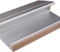
Another material option is the standard electrical cable tray, typically made of metal or aluminum. These are sturdy and durable, providing strong support for heavy cables. Electrical trays are commonly used in industrial settings where multiple cables need to be managed in a large space.
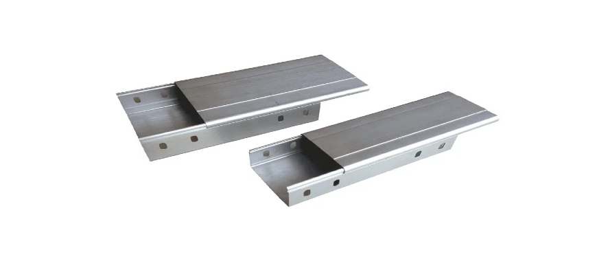
Enclosed trays are another choice when you need to protect cables from environmental factors such as moisture, dust, or debris. These trays offer added security and are often used in harsh or outdoor environments where protection is a priority. Adding cable tray cladding to the system provides an additional layer of protection and enhances the overall safety and aesthetic of the installation. The material selection should be based on the specific needs of your installation, whether it’s for durability, flexibility, or protection.
By using the correct tools and selecting appropriate materials, your custom-built cable tray system can offer lasting reliability and performance for a wide range of applications.
How to Build Cable Trays on a Wall
Step-by-Step Instructions on Wall-Mounted Cable Tray Installation
When you build cable trays, wall-mounted installations are a common choice for both industrial and residential settings. To begin, carefully measure and mark the installation points on the wall. These marks should align with the cable tray’s support brackets, ensuring even weight distribution and proper support. Use a measuring tape and level to guarantee accuracy.
Next, drill holes into the marked points, making sure they are evenly spaced. Insert wall anchors or appropriate fasteners, depending on the wall’s material, to provide a sturdy foundation for the brackets. Once the anchors are secured, attach the mounting brackets using screws or bolts, ensuring each bracket is firmly fixed to the wall. After the brackets are installed, carefully position the cable trays on top of them, making sure they are level and securely placed.
For longer runs of cable trays, connect multiple tray sections using the provided connectors, ensuring smooth transitions between sections. Once the trays are fully installed, place the cables within them, organizing the wires to avoid tangling. Secure the cables in place with cable ties or clamps to prevent movement or wear over time.
Tips for Ensuring Structural Integrity and Safety
When you build cable trays, ensuring structural integrity and safety is crucial. First, always verify that the wall can support the weight of the cable tray and the cables. For heavier installations, consider adding additional supports or using stronger fasteners to prevent sagging or collapse over time.
Another safety tip is to avoid overloading the trays. Calculate the total weight of the cables you’ll be running through the tray and ensure that it falls within the manufacturer’s load capacity. Overloading can weaken the tray and increase the risk of accidents.
In addition, make sure the trays are positioned away from heat sources or any potential hazards that could damage the cables. Proper spacing between cables is also important to avoid heat buildup, which could lead to overheating or short circuits. By following these steps and tips, your wall-mounted cable tray system will offer long-lasting durability and safety.
Creating Build Cable Trays Installation Drawings
Why Installation Drawings Are Critical for Large-Scale Projects
When you build cable trays for large-scale projects, installation drawings play a vital role in ensuring successful implementation. These drawings provide a clear visual layout of where and how the cable trays should be installed, minimizing the chances of errors during the construction process. In complex environments such as industrial facilities or large buildings, accurate installation drawings help coordinate the placement of trays with other systems, such as electrical wiring and HVAC ducts, preventing interference or overlap.
For larger projects, precise drawings also contribute to more efficient resource planning. By mapping out the route of the cable trays, materials can be allocated correctly, reducing waste and unnecessary purchases. Furthermore, installation drawings serve as a communication tool among team members, ensuring that everyone involved in the project follows the same plan, thus avoiding costly delays or mistakes.
How to Prepare and Use Cable Tray Installation Drawings Effectively
When you build cable trays, preparing detailed installation drawings is essential for guiding the process. Start by identifying the key points of the installation area, such as the walls, ceilings, and any obstacles that might interfere with the tray’s placement. Use these reference points to design the cable tray route, ensuring that it follows a logical and efficient path.
It is important to mark where each support bracket, joint, or bend will be placed within the drawing. This helps installers visualize the entire structure and prevents issues during the actual installation. Include clear measurements in your drawings, noting the distances between each support and the total length of the cable trays needed for the project.
Once the drawings are prepared, they should be used as a step-by-step guide during the installation process. Installers should regularly reference the drawings to ensure the trays are positioned correctly, and adjustments can be made based on the actual site conditions. By using these installation drawings effectively, the process of building cable trays becomes more organized and efficient, ensuring a successful outcome for even the largest projects.
Capsule Cable Tray: Effective Solution for Cable Management
Building Wire Mesh Cable Trays
Advantages of Wire Mesh Cable Trays for Ventilation and Ease of Installation
When you build cable trays using wire mesh, there are several advantages that make them an excellent choice for many applications.
Improved Ventilation: Wire mesh cable trays allow for superior airflow around the cables. This helps prevent overheating, which is essential for maintaining the longevity of electrical systems. In environments with high temperatures, proper ventilation can also reduce the risk of fire hazards.
Lightweight and Flexible: Wire mesh trays are typically lighter than other types of cable trays, making them easier to transport and handle during installation. Their flexibility allows them to be cut and shaped on-site, which is beneficial for fitting into tight or irregular spaces.
Ease of Installation: The open structure of wire mesh trays simplifies the installation process. Cables can be easily inserted and routed through the tray without the need for additional tools or fasteners, saving time and effort.
Cost-Effective: Wire mesh cable trays are often more affordable than other types of trays, especially for large-scale installations. Their lightweight nature also reduces shipping costs, making them a budget-friendly option for projects with limited resources.
Durability: Despite their lightweight design, wire mesh trays are strong and capable of supporting significant cable loads. They offer reliable protection for cables while also being resistant to corrosion and damage in harsh environments.
Best Practices for Building and Securing Wire Mesh Trays
When you build cable trays using wire mesh, following best practices ensures the system is secure and efficient. Start by measuring and cutting the wire mesh trays to the required length for your installation. Use proper cutting tools to create clean edges that won’t damage cables during installation.
Once cut, mount the support brackets on walls, ceilings, or floors, making sure they are spaced evenly to prevent sagging. Attach the wire mesh tray securely to the brackets, using appropriate fasteners to avoid movement. Ensure that the tray remains level throughout the installation to prevent uneven cable placement.
It’s important to secure the cables within the tray using cable ties or clips. This prevents the cables from shifting and helps maintain a neat arrangement. Finally, always check the load capacity of the wire mesh trays to ensure they are not overloaded, which could compromise the integrity of the system. By following these best practices, you can ensure a reliable and durable cable management solution.
Installing Industrial Build Cable Trays
Insights into the Installation Process for Industrial Cable Trays
When you build cable trays for industrial settings, the installation process requires careful planning and execution. Industrial cable trays often need to support large volumes of cables, so choosing the right tray type and placement is critical. Begin by mapping out the cable routes and identifying the ideal locations for support brackets. These should be spaced at intervals that ensure stability, even when the trays are fully loaded with cables.
Next, ensure that the tray is securely fastened to the support brackets using bolts or screws, depending on the tray material. It’s important to check that the cable trays are level and aligned to prevent future cable damage or interference. When installing multiple sections, use connectors to join the trays, ensuring a seamless flow for cable routing. In industrial environments, the trays should also be grounded to prevent electrical hazards.
Focus on Heavy-Duty Applications and Electrical Safety Considerations
Industrial applications demand robust cable tray systems that can handle heavy loads and harsh conditions. When you build cable trays for these settings, you need to account for the weight of the cables and any additional equipment that may be installed on or near the trays. Ensure that the trays and supports can handle the total weight without sagging or compromising structural integrity.
Electrical safety is paramount. Make sure that all cables are routed properly to avoid crisscrossing, which could lead to overheating. Additionally, it’s essential to use fire-retardant materials where necessary, especially in high-risk environments. Regular inspections and maintenance should be planned to ensure the ongoing safety and reliability of the system.
Enclosed Build Cable Trays Systems
Benefits of Enclosed Trays for Protecting Sensitive Cables
When you build cable trays for sensitive electrical systems, enclosed trays offer several advantages. They protect cables from dust, moisture, and physical damage, which is crucial in environments where cables are exposed to harsh conditions. Enclosed trays also help prevent unauthorized access to sensitive cables, adding a layer of security in industrial settings.
For sensitive applications such as data centers or outdoor industrial setups, enclosed trays ensure that cables remain functional and free from external interference. The added protection also helps prolong the lifespan of cables, reducing maintenance costs over time.
Installation Tips for Enclosed Tray Systems in Harsh Environments
Installing enclosed trays requires additional care, especially in challenging environments like outdoor facilities or areas exposed to high humidity or dust. When you build cable trays for such settings, ensure that the enclosure is properly sealed to prevent contaminants from entering. Use weather-resistant fasteners to secure the trays, and check that all connections between sections are airtight.
It’s also important to leave adequate space within the enclosure for airflow, helping to prevent cables from overheating. Regular inspections are essential in harsh environments to detect any wear or damage to the enclosure that could compromise the cables inside. Following these tips ensures that your enclosed tray system provides optimal protection and longevity in tough industrial environments.
Electrical Build Cable Trays Installation Guide
Key Considerations for Electrical Cable Tray Installation
When you build cable trays for electrical systems, several factors need to be considered to ensure a safe and efficient installation. The first step is choosing the right type of cable tray based on the size and weight of the cables it will support. Electrical cables vary in size, and the tray must be able to handle the total load without sagging.
Proper spacing between the support brackets is essential for maintaining stability, especially with long runs of heavy cables. Ensure the trays are aligned properly and that any bends or turns are smooth to avoid damaging the cables during installation. Additionally, all electrical cable trays should be grounded according to safety regulations, as this prevents electrical shock hazards and ensures system reliability.
Focus on Maintaining Safety and Compliance with Standards
When you build cable trays, safety is a top priority, particularly for electrical installations. Compliance with electrical safety standards is crucial to avoid potential hazards such as fires, short circuits, or electric shock. Always follow local and international electrical codes when selecting materials and placing the trays.
Avoid overloading the trays with too many cables, as this can cause overheating and lead to equipment failure. Furthermore, ensure proper ventilation around the cables, especially when dealing with high-voltage systems, to prevent heat buildup. Secure all cables within the tray with ties or clamps to avoid movement that can lead to wear and tear. Regular testing of grounding connections is also necessary to ensure ongoing safety.
Maintenance and Inspection of Build Cable Trays Systems
Best Practices for Maintaining Cable Trays Post-Installation
After you build cable trays, regular maintenance is essential to ensure their continued performance. One best practice is to periodically check for any signs of wear or damage to both the trays and the cables they hold. Over time, exposure to environmental factors or heavy loads may cause the trays to weaken or bend.
It’s important to make sure that all supports and fasteners remain securely in place. Loose brackets or screws can compromise the structural integrity of the tray system, leading to potential hazards. Re-secure or replace any parts that show signs of deterioration to keep the cable tray system functioning effectively.
Tips for Regular Inspections to Ensure Cable Safety and Longevity
Regular inspections are critical for ensuring the long-term safety of your cable tray system. At least twice a year, inspect the entire system for any signs of corrosion, cracks, or misalignment. When you build cable trays, especially in harsh environments, this routine becomes even more crucial.
During inspections, check that the cables remain neatly arranged and properly secured within the trays. Pay special attention to areas where cables may rub against the tray’s edges, as this can lead to insulation damage. Ensure that no cables are exposed to excessive heat or moisture, which could lead to degradation. By following these inspection tips, you can significantly extend the life of both the trays and the cables, ensuring a safe and reliable electrical system.
Classic Cable Tray: Reliable Support for Your Installations
The Importance of Building Custom Cable Trays
When you build cable trays, you create a tailored solution that perfectly matches the needs of your project, whether for industrial or residential applications. Custom-built trays offer greater flexibility in terms of design and materials, allowing you to ensure that they are both cost-effective and suitable for your specific requirements. By investing time and effort into building your own cable trays, you can achieve better cable management, increased safety, and a longer lifespan for your electrical systems. The process of building trays also provides the ability to adapt to different environments, ensuring that your cable infrastructure remains organized and secure. This is especially important when considering the role of cable tray in building, where the system must meet both functional and regulatory standards for optimal performance.
Encouragement to Follow Best Practices for Safety and Efficiency
As you build cable trays, it’s crucial to follow best practices to ensure that your installation is both safe and efficient. Proper planning, careful material selection, and adherence to installation guidelines help minimize risks while improving overall system performance. Ensure that all cables are properly secured and that the trays are installed with stability and precision. Regular maintenance and inspections will further guarantee the long-term success of your cable management system. By focusing on these principles, you can create a reliable and safe solution that meets the demands of modern infrastructure while optimizing the efficiency of your electrical systems.
How to Build Cable Trays with a 90-Degree Bend
In the construction of cable tray systems, a 90-degree bend is a crucial component that allows for smooth directional changes while maintaining structural integrity and cable support. Without properly executed bends, cable trays can become inefficient, leading to excessive cable strain, potential damage, or non-compliance with safety standards.
Creating a precise 90-degree bend is not just about bending the metal—it involves careful planning, accurate cutting, and secure fastening to ensure durability and safety. Additionally, different types of cable trays, such as ladder trays, perforated trays, and solid-bottom trays, require slightly different methods to achieve the bend while maintaining load capacity.
This guide explores the importance of 90-degree bends, the step-by-step process to create one, and key factors to consider to ensure a high-quality installation. By following these best practices, you can build cable trays that are both functional and compliant with industry standards.
Why Is a 90-Degree Bend Necessary in Cable Tray Construction?
In most electrical and industrial installations, cable trays are rarely installed in a straight line from start to finish. Various obstacles such as walls, machinery, support structures, or changes in floor level require the tray system to adapt and follow a specific routing path. A 90-degree bend is one of the most common directional adjustments, providing the following benefits:
- Optimized Cable Routing: Ensures cables are properly organized and directed toward their intended destinations without excessive slack or tangling.
- Structural Adaptability: Allows the cable tray to navigate around architectural and mechanical obstructions, ensuring efficient use of space.
- Prevention of Cable Stress: Without a proper bend, cables could be forced into tight corners or unsupported sections, leading to insulation damage or mechanical wear over time.
- Compliance with Electrical Standards: Many industry codes and standards require smooth directional changes to ensure safe and efficient cable management.
A poorly executed 90-degree bend can result in structural weaknesses, improper cable support, and long-term maintenance issues. That’s why it’s important to follow a precise method when creating bends in cable trays.
Step-by-Step Guide to Making a 90-Degree Bend in a Cable Tray
Properly creating a 90-degree bend in a cable tray requires the right tools and techniques. Below are the essential steps to ensure accuracy and durability.
Measure and Mark the Bend Area
Before making any cuts, you must determine the exact location of the bend.
- Use a measuring tape to find the precise point where the tray needs to turn.
- Mark the area with a pencil or marker to guide the cutting process.
- Double-check measurements to ensure the bend aligns with the overall tray layout.
Cut the Tray Segments
The cutting method depends on the type of cable tray being used:
- For ladder trays: Identify and remove the rungs in the bend area using a hacksaw or an angle grinder.
- For perforated trays: Cut V-shaped notches along the sides where the bend will occur, allowing for easier manipulation.
- For solid-bottom trays: Create relief cuts along the bottom and sides to facilitate bending without deforming the tray structure.
Bend the Tray Carefully
Once the necessary cuts are made, the bending process begins:
- Manually bend the tray if working with aluminum or lightweight steel.
- Use a bending tool or mechanical press for heavier-duty trays to ensure an even curve.
- Check the angle with a square tool to confirm an accurate 90-degree bend.
Secure the Bend for Structural Integrity
After bending the tray to the desired angle:
- Use bolted splices or clamps to reinforce the bend and maintain tray strength.
- Ensure all fasteners are tightened to prevent movement or shifting after installation.
- Test the stability by applying slight pressure to confirm that the structure remains firm.
Key Considerations When Making a 90-Degree Bend
While the steps above outline the technical process, additional factors must be considered to ensure safety, durability, and compliance.
Maintain Load Capacity and Structural Strength
When making a 90-degree bend, excessive cutting or weak connections can compromise the tray’s ability to support cables. Always reinforce the bend properly using splices, brackets, or welded joints where necessary.
Ensure Proper Cable Support
A well-executed bend should not cause cables to hang loosely or bend at sharp angles. Ensure the tray provides consistent cable support throughout the bend to avoid sagging or excessive stress on electrical conductors.
Deburr and Smooth Edges
Cutting metal trays can leave sharp edges that pose a risk to cables and installers. Always use a file or deburring tool to smooth out rough surfaces and prevent potential insulation damage.
Follow Safety Guidelines
Handling and cutting cable trays require proper safety precautions:
- Wear protective gloves and safety goggles to prevent injury from metal shards.
- Use stable support structures when cutting or bending to maintain precision.
- Follow manufacturer guidelines for cutting and bending specific tray materials.
A 90-degree bend is a fundamental aspect of cable tray construction, ensuring that the system can efficiently adapt to different layouts and obstacles. Proper execution involves accurate measurement, precise cutting, controlled bending, and strong reinforcement to maintain the tray’s integrity and cable support.
By following these best practices, you can confidently build cable trays that are safe, reliable, and compliant with industry standards. Whether in industrial, commercial, or residential settings, mastering the 90-degree bend technique ensures a seamless cable management system that will last for years.
Building Cable Trays: The Necessity and Installation of Serpentine Cable Trays
Serpentine cable trays play a crucial role in modern electrical installations, offering flexibility, space efficiency, and enhanced cable management. Unlike standard straight cable trays, serpentine trays are designed to navigate complex layouts, making them ideal for environments with limited space or multiple obstacles. They are commonly used in industrial facilities, commercial buildings, and data centers, where cable routing must adapt to structural constraints. This article explores the necessity of serpentine cable trays, their installation process, key precautions to consider, and their various applications. By understanding these aspects, engineers and electricians can ensure efficient and safe installations, optimizing cable performance and system reliability.
The Necessity of Serpentine Cable Trays
Serpentine cable trays are essential in electrical infrastructure due to their adaptability and efficiency. They allow cables to be routed around obstacles, reducing the need for excessive conduit bending or multiple junctions. This flexibility makes them invaluable in confined spaces where traditional cable trays would be impractical.
Key Benefits of Serpentine Cable Trays:
- Space Optimization: Their curved design allows efficient cable management in areas with limited space, such as ceilings with existing HVAC ducts or machinery-filled industrial settings.
- Reduced Cable Stress: Unlike sharp-angle bends in traditional trays, serpentine trays offer smooth transitions, minimizing stress on cables and reducing the risk of insulation damage.
- Enhanced Aesthetic and Organization: The sleek design of serpentine trays improves the visual appeal of cable management in open installations such as commercial spaces and data centers.
- Lower Installation Costs: They eliminate the need for multiple connectors and complex conduit routing, making installations faster and more cost-effective.
By addressing these challenges, serpentine cable trays enhance the reliability and longevity of electrical systems.
How to Install Serpentine Cable Trays
Proper installation is critical to ensuring that serpentine cable trays function optimally and comply with safety standards. The installation process involves careful planning, securing supports, and ensuring smooth cable transitions.
Step-by-Step Installation Process:
Planning and Layout Design:
- Assess the installation site and identify obstacles such as beams, walls, and other utilities.
- Determine the optimal route for the tray, considering access points and cable entry/exit points.
- Ensure compliance with NEC Article 392, which governs cable tray installations.
Mounting the Tray Supports:
- Secure tray supports at regular intervals, typically 5 to 10 feet (1.5 to 3 meters) apart, to prevent sagging.
- Use brackets or hangers to maintain alignment and structural integrity.
Installing the Serpentine Cable Tray:
- Align the tray with the pre-planned layout, making necessary adjustments to accommodate curves and bends.
- Secure the tray sections with proper fasteners to ensure stability.
- Maintain clearance from heat sources and high-voltage equipment to prevent interference.
Routing and Securing Cables:
- Lay cables within the tray while ensuring proper separation between power, control, and communication lines.
- Use cable ties or clamps to prevent movement and reduce mechanical strain.
- Ensure proper labeling for easier maintenance and troubleshooting.
Final Inspection and Testing:
- Verify that all supports and connections are secure.
- Check grounding and bonding compliance as per NEC 392.60 to prevent electrical hazards.
- Conduct an insulation resistance test to ensure cables are free from damage.
Installation Precautions for Serpentine Cable Trays
While serpentine cable trays offer significant advantages, improper installation can lead to safety hazards and operational inefficiencies. Following essential precautions ensures a durable and compliant installation.
Key Installation Precautions:
- Ensure Proper Load Capacity: Overloading the tray can cause sagging, cable damage, and overheating. Adhere to NEC 392.22 fill limits to maintain safe cable distribution.
- Allow Adequate Bending Radius: Avoid excessive bending of cables, especially for fiber optics and data cables, to prevent signal loss and damage.
- Maintain Spacing Between Different Cable Types: Keep power and communication cables separate to minimize electromagnetic interference (EMI).
- Secure Cables Properly: Loose cables can lead to mechanical wear and pose fire risks. Use approved fastening methods to keep cables neatly arranged.
- Consider Environmental Conditions: In corrosive environments, choose trays with protective coatings such as hot-dip galvanized or PVC-coated steel to extend tray life.
- Regular Inspection and Maintenance: Periodic checks ensure cable integrity, prevent potential faults, and maintain compliance with electrical codes.
By following these precautions, electricians can maximize the efficiency and safety of serpentine cable tray installations.
Applications of Serpentine Cable Trays
Serpentine cable trays are widely used in industries that require efficient, adaptable, and aesthetically appealing cable management solutions. Their unique design makes them suitable for various applications where traditional cable trays may not be feasible.
Common Applications:
- Industrial Facilities: Factories, power plants, and processing plants use serpentine trays to navigate machinery and equipment while maintaining organized cable routing.
- Data Centers: These trays help manage large volumes of data and power cables in server rooms, ensuring smooth airflow and reducing overheating risks.
- Commercial Buildings: Offices, shopping malls, and public spaces benefit from the sleek, space-saving design of serpentine trays for lighting, networking, and power distribution.
- Transportation Infrastructure: Airports, subway systems, and tunnels rely on serpentine trays to route cables around structural constraints while ensuring easy maintenance access.
- Healthcare and Laboratories: Hospitals and research facilities use serpentine trays to organize power and communication cables while maintaining hygiene and accessibility.
Each of these applications demonstrates the versatility and efficiency of serpentine cable trays in modern electrical installations.
Serpentine cable trays provide an innovative solution for complex cable management, offering flexibility, space efficiency, and improved organization. Their ability to navigate obstacles, reduce cable stress, and enhance system aesthetics makes them indispensable in various industries. Proper installation, adherence to safety precautions, and understanding their applications are crucial for ensuring reliable performance and compliance with electrical standards. By integrating serpentine cable trays into electrical infrastructure, businesses can achieve safer, more efficient, and cost-effective cable management solutions.
FAQs About Build Cable Trays
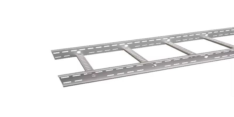
There are three primary types of cable trays commonly used in various installations: ladder trays, solid-bottom trays, and wire mesh trays. Ladder trays are designed with rungs that allow cables to rest on the support, offering superior ventilation. They are ideal for environments where heat dissipation is crucial. Solid-bottom trays provide complete protection to the cables, shielding them from dust, debris, or moisture, making them perfect for sensitive or outdoor applications. Wire mesh trays are flexible and lightweight, making them easy to install in tight spaces or areas where frequent changes to the cable system might occur. Each type of tray has specific applications, and selecting the right one depends on the environment and the cable protection needs.
Cable trays are typically manufactured from steel, aluminum, or fiberglass-reinforced plastic. The material choice depends on the environmental conditions and load requirements. The process begins with shaping the raw material into long strips or sections that will form the structure of the tray. For steel and aluminum trays, these strips are often formed into ladder-like rungs or solid-bottom panels. Fiberglass-reinforced trays are molded into shape using heat and pressure. Once the basic tray form is created, it undergoes processes such as galvanization or coating to enhance durability and resistance to corrosion. The final product is strong, lightweight, and suitable for supporting a variety of cables in different environments.
To properly prepare a cable tray, start by determining the route and layout where the tray will be installed. Measure the distance, ensuring that there are no obstacles along the way. Based on the installation environment, select the appropriate type of tray, whether ladder, solid-bottom, or wire mesh. Gather all the necessary tools, such as screwdrivers, wrenches, and brackets for support. Before installation, make sure the walls or ceilings are prepared for mounting. Mark the points where the tray will be fastened and ensure that the supports are placed evenly to avoid sagging. Ensure the cables are organized and secured within the tray to prevent damage during use.
Cable trunking and cable trays serve similar purposes but differ in design and applications. Cable trays are open structures that allow easy installation and maintenance of cables. They offer better ventilation, which is especially important in environments where heat buildup is a concern. Cable trunking, on the other hand, is an enclosed system that completely houses the cables. It offers superior protection from external elements such as dust, moisture, or physical damage. Trunking is ideal for situations where aesthetics or protection from external factors are priorities, such as in office settings or outdoor environments. The choice between the two depends on the level of protection and access required for the cable system.
The best material for cable trays depends on the installation environment and durability requirements. Common materials include:
Galvanized Steel: Cost-effective and provides good corrosion resistance. Ideal for indoor and industrial use.
Stainless Steel: Best for highly corrosive environments like chemical plants and offshore platforms due to its superior rust resistance.
Aluminum: Lightweight, corrosion-resistant, and easy to install, making it suitable for commercial and outdoor applications.
FRP (Fiber Reinforced Plastic): Non-conductive, lightweight, and highly resistant to chemicals, making it ideal for corrosive and electrical-sensitive environments.
Each material has its benefits, so selection should consider environmental exposure, load-bearing capacity, and budget. For harsh environments, stainless steel or FRP is preferable, while for general industrial applications, galvanized steel is a cost-effective choice.
The spacing of cable tray rungs depends on the type and size of cables being supported. Standard rung spacing typically ranges from 9 inches (225mm) to 12 inches (300mm) center-to-center. For heavier cables or higher loads, 6-inch (150mm) spacing may be used.
Proper spacing is crucial for:
Supporting cable weight adequately
Preventing excessive sagging
Allowing airflow to reduce heat buildup
Ladder-type trays generally have standard spacing of 9 inches, while larger or custom trays may vary based on manufacturer recommendations and load calculations. The National Electrical Code (NEC) and industry standards should be followed to ensure compliance with structural and safety requirements.
Tray cables are specifically designed for installation in cable trays and do not generally require conduit. However, there are circumstances where conduit might be necessary:
When transitioning from the tray to electrical equipment to protect against mechanical damage.
In areas with excessive moisture, dust, or chemicals where additional protection is needed.
For compliance with local electrical codes, some installations may mandate conduit in specific areas.
NEC (National Electrical Code) Article 392 governs the use of cable trays, and if tray-rated (TC) cables are used, they can be installed without conduit in most cases. However, proper securing and spacing within the tray are necessary to ensure safety and efficient operation.
The minimum thickness of a cable tray depends on the material and load requirements. Standard thicknesses are:
Galvanized or Stainless Steel: Typically 1.5mm to 3mm (14 to 16 gauge).
Aluminum: Generally 2mm to 3mm depending on span and load.
FRP (Fiber Reinforced Plastic): Commonly 3mm to 5mm for heavy-duty applications.
For standard commercial installations, 2mm (14-gauge) galvanized steel is widely used, but for industrial and heavy-load environments, 2.5mm to 3mm thickness is preferred. Proper selection ensures adequate strength to support cable loads while maintaining compliance with safety regulations.
Yes, cable trays made of metal must be properly grounded (earthed) to ensure safety and compliance with electrical standards. Earthing serves the following purposes:
Prevents electrical shock hazards in case of faults.
Dissipates stray currents to protect cables and equipment.
Ensures compliance with NEC and IEC standards for electrical safety.
Earthing methods include:
Bonding cable trays to the grounding system using grounding clamps or lugs.
Using a dedicated grounding conductor along the tray length.
Ensuring electrical continuity between tray sections with bonding jumpers.
FRP trays do not require grounding as they are non-conductive. However, metal trays must always be bonded properly to avoid electrical risks.
The maximum span of a cable tray depends on the material, type of tray, and load capacity. Typical span distances include:
Steel cable trays: 6 to 12 feet (1.8m to 3.6m) between supports.
Aluminum trays: 6 to 10 feet (1.8m to 3m), as they have lower load-bearing capacity.
FRP trays: 6 to 8 feet (1.8m to 2.4m) due to flexibility.
Larger spans may require reinforced tray designs or additional support. For heavy loads or long spans, additional support brackets or beams should be installed to prevent sagging and ensure long-term durability.
The best method for cutting cable trays depends on the material:
For steel trays: Use an angle grinder with a cutting disc or a bandsaw for precise cuts.
For aluminum trays: A hacksaw or reciprocating saw is sufficient.
For FRP trays: A carbide-tipped saw blade is recommended.
Best practices for cutting include:
Marking cut lines clearly for accuracy.
Using appropriate safety gear (gloves, goggles).
Deburring edges to prevent injury and cable damage.
Cutting should be done in a well-ventilated area, especially for FRP, as dust can be hazardous.
Perforated cable trays offer several advantages:
Better Ventilation: Helps dissipate heat and prevent cable overheating.
Reduced Weight: Lighter than solid-bottom trays while maintaining strength.
Easy Cable Management: Openings allow for flexible entry and exit points.
Cost-Effective: Provides good support with minimal material usage.
They are widely used in commercial and industrial setups where airflow and ease of cable installation are priorities.
To determine the correct cable tray size, follow these steps:
Calculate the total cross-sectional area of cables to be installed.
Add 25-30% extra space for future expansion.
Choose the appropriate tray width based on the total area.
Ensure proper load capacity to handle cable weight.
Example: If the total cable area is 200 cm², selecting a 300mm (30cm) wide tray allows extra space for future additions. Always refer to NEC or IEC guidelines for proper sizing.
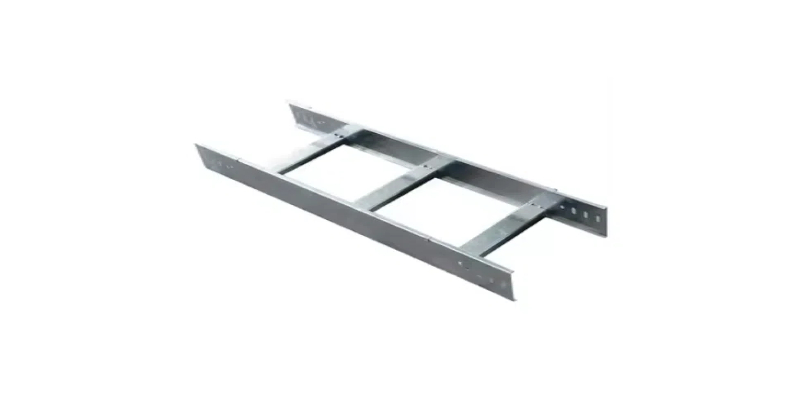
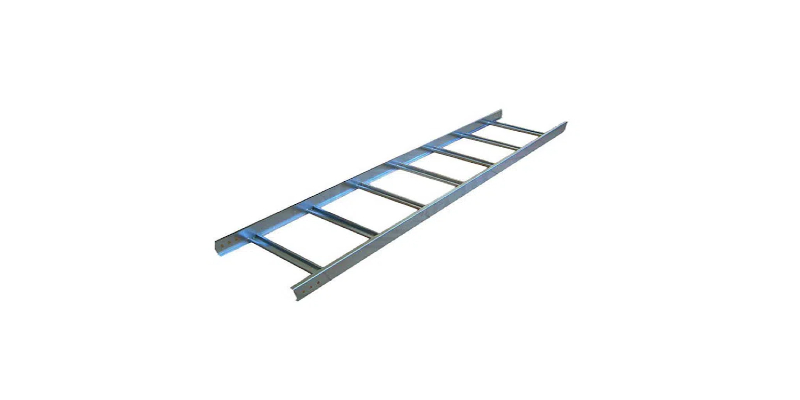
A cable ladder and a cable tray differ mainly in design, load capacity, and application. A cable ladder consists of two parallel side rails connected by rungs, resembling a ladder. This open structure provides excellent ventilation, making it ideal for heavy-duty industrial applications where large cables need efficient heat dissipation. Cable ladders also have a higher load-bearing capacity, making them suitable for long cable runs.
On the other hand, a cable tray has a solid or perforated bottom with side rails. Perforated trays offer partial ventilation while providing more support for smaller cables. Solid-bottom trays offer maximum protection against dust and debris but limit airflow. Cable trays are commonly used in commercial and industrial settings where moderate cable support and organization are needed.
In summary, cable ladders are best for heavy cables in harsh environments, while cable trays provide better protection and organization for smaller or bundled cables.
Cable trays support various types of tray-rated cables (TC), including power, control, and communication cables. National Electrical Code (NEC) Article 392 specifies the types of cables that can be installed in cable trays, such as Type TC (Tray Cable), Type ITC (Instrumentation Tray Cable), Type MC (Metal-Clad), and Type MI (Mineral-Insulated). These cables are specifically designed to be installed in tray systems and must meet flame-retardant and mechanical durability standards. TC cables, for example, have thermoplastic or thermoset insulation and a protective jacket, making them suitable for industrial environments. NEC also allows certain non-tray-rated cables in trays under specific conditions, such as being installed inside a protective conduit. Choosing the correct cable depends on environmental conditions, voltage requirements, and industry standards. Always refer to NEC and manufacturer guidelines to ensure compliance with electrical codes and safety requirements.
The thickness of a cable tray’s coating depends on the material and the type of protective layer applied. Galvanized steel trays typically have a zinc coating ranging from 1.5 to 3.5 mils (0.038 to 0.089 mm) for general use, while hot-dip galvanized coatings can be thicker, around 2.0 to 5.0 mils (0.05 to 0.127 mm), providing enhanced corrosion resistance. Aluminum cable trays do not require additional coatings due to their natural oxide layer, which prevents corrosion. For extreme environments, such as chemical plants or offshore applications, epoxy or PVC coatings may be used, with thicknesses ranging from 5 to 20 mils (0.127 to 0.508 mm). The choice of coating depends on environmental conditions, exposure to chemicals, and durability requirements. Selecting the right coating ensures longevity, safety, and compliance with electrical and industry standards.
Yes, tray cable can be run exposed under specific conditions outlined in NEC Article 336. TC-rated cables are designed for exposed runs when properly supported and protected from physical damage. Exposed tray cables must typically be installed at least 7 feet (2.1 meters) above the floor unless further protection, such as conduit or raceway, is provided. Additionally, TC-ER (Tray Cable – Exposed Run) cables are specially designed with reinforced jackets, allowing them to be run outside a cable tray for short distances without additional conduit protection. However, the installation must comply with local codes, ensuring the cable is secured, properly supported, and away from hazardous locations. In industrial and commercial settings, tray cables are often used for control circuits, power distribution, and signal transmission, making them an efficient choice when installed correctly according to NEC regulations.
The NEC regulates cable tray fill to ensure proper ventilation, heat dissipation, and safety. NEC Article 392.22 provides specific guidelines based on cable type and tray width. For multiconductor cables, the sum of the cable diameters should not exceed 50% of the tray’s width. For single conductors, spacing rules apply, and no more than 30% fill is allowed for continuous rigid cables. Ventilated trays must follow fill percentages based on cross-sectional areas to maintain proper heat dissipation and prevent overheating. Additionally, proper spacing must be maintained to prevent mechanical damage and ensure easy access for maintenance. Overloading trays can cause excessive heat buildup, insulation degradation, and fire hazards, making NEC compliance essential. It’s crucial to verify local codes and industry standards when designing cable tray systems to ensure electrical safety and long-term performance.
Yes, NEC Article 392.60 mandates that all cable trays be bonded to the electrical grounding system to ensure safety. Cable trays made of metal can conduct fault currents, so proper grounding prevents electrical hazards, such as shocks and fires. Bonding jumpers must be installed at every tray section and connection point, ensuring electrical continuity throughout the system. If cables with metallic sheaths or armor are present, they must also be grounded to the tray. In cases where a non-metallic tray is used, a dedicated ground conductor must be installed alongside the cables. Proper bonding reduces the risk of electrical faults, improves system reliability, and meets compliance standards. Regular inspections should be performed to ensure all grounding connections remain secure and free from corrosion.
The minimum distance between cable trays depends on the type of cables being installed, the voltage level, and maintenance accessibility. NEC guidelines recommend a spacing of at least 12 inches (30 cm) horizontally between parallel trays to allow for heat dissipation and prevent electromagnetic interference. Vertical spacing should be at least 6 inches (15 cm), ensuring adequate clearance for cable installation and maintenance. When running power and communication cables in the same area, separation is necessary to prevent signal interference. In hazardous locations, additional spacing may be required based on environmental conditions. Proper spacing is essential for airflow, minimizing overheating, and ensuring compliance with electrical safety standards.
Yes, cable splices are allowed in cable trays, but they must comply with NEC Article 300.13 and 392.56. Splices must be enclosed in junction boxes, splice boxes, or other NEC-approved enclosures to protect against mechanical damage and environmental exposure. The box or enclosure should be securely fastened to the tray or a nearby support structure. Open-air splicing is not permitted due to the risk of electrical faults, arcing, and potential fire hazards. When splicing in a tray, proper strain relief and mechanical support must be provided to prevent cable damage. Additionally, all splices should be tested for continuity and insulation resistance to ensure safe operation. NEC compliance ensures the longevity and reliability of electrical systems while minimizing safety risks.
Standard tray cable (TC) is not rated for direct burial unless explicitly marked as TC-DB (Tray Cable – Direct Burial). NEC Article 336 specifies that only cables with a direct burial rating can be installed underground without additional conduit protection. TC-DB cables have thicker jackets and insulation to resist moisture, soil pressure, and environmental damage. If standard tray cable needs to be buried, it must be installed inside a conduit or duct system to provide the necessary protection. Always check manufacturer specifications and NEC guidelines before direct-burying any cable to ensure compliance and safety.
Certain cables should not be placed in the same cable tray due to electrical interference, heat buildup, and safety risks. NEC Article 392.80 specifies separation requirements. High-voltage power cables should not be installed alongside low-voltage communication or data cables due to the risk of electromagnetic interference (EMI). Fire alarm circuits must be routed separately from other electrical systems to prevent accidental failures. Additionally, hazardous location cables (such as those used in explosive environments) should not share a tray with standard industrial cables. Ensuring proper separation minimizes electrical noise, enhances system performance, and improves safety compliance.
Cable tray supports must be installed at intervals to prevent sagging and ensure stability. NEC Article 392.30(B) states that supports should be placed every 5 feet (1.5 meters) to 10 feet (3 meters) depending on the tray material, load capacity, and environmental conditions. Heavier trays with large cable loads require closer support spacing, typically around 5 feet (1.5 meters), while lighter-duty trays may allow for wider spacing. Trays exposed to vibration, wind, or seismic activity may require additional supports to maintain structural integrity. Proper support placement ensures cable trays remain secure, preventing mechanical strain on cables and extending system longevity.
Yes, cable tray runs should be installed before conductors to ensure proper support, organization, and compliance with NEC regulations. Installing the trays first allows for accurate layout planning, ensuring that trays are securely mounted, properly spaced, and supported according to load requirements. This approach also helps in routing cables efficiently, reducing unnecessary bends and stress on conductors. Additionally, pre-installing trays ensures that bonding and grounding connections are correctly set up before conductors are pulled. If cables are installed before trays, there is a risk of mechanical damage, misalignment, and potential violations of electrical codes. A well-planned installation process improves safety, maintenance accessibility, and system reliability. Once the trays are in place, cables can be neatly arranged, secured with proper fasteners, and protected from environmental hazards. Following this sequence ensures compliance with NEC Article 392 and enhances the longevity of the cable management system.
While cable trays offer efficient cable management, they have some disadvantages. One major concern is exposure to environmental factors such as moisture, dust, and chemicals, which can lead to corrosion and degradation of cables. Unlike conduit systems, trays do not fully enclose cables, making them susceptible to mechanical damage and requiring additional protection in harsh environments. Another disadvantage is limited EMI shielding, as cable trays do not inherently block electromagnetic interference, which can affect sensitive communication or control circuits. Additionally, proper installation and maintenance are required to prevent overloading, sagging, and overheating. Cable trays also demand regular cleaning and inspections to ensure cables are secure and free from obstructions. In certain industries, fire safety regulations may require fire-resistant coatings or barriers, increasing installation costs. Despite these challenges, proper design, material selection, and adherence to NEC guidelines can mitigate most disadvantages.
Cable trays come in various standard sizes, typically ranging from 6 inches to 36 inches wide and 3 inches to 6 inches deep, depending on the application. The most common widths are 12 inches, 18 inches, and 24 inches, while standard depths include 3 inches and 5 inches. The length of each tray section usually varies between 10 feet and 12 feet. These dimensions comply with NEMA (National Electrical Manufacturers Association) and NEC standards. Selecting the correct size depends on the cable fill requirements, load capacity, and environmental factors. Overloading a tray can lead to excessive heat buildup, so NEC Article 392.22 provides guidelines for allowable fill percentages. Larger trays may be required for industrial applications where multiple cable types need to be accommodated, while smaller trays are suitable for low-voltage or control wiring. Proper sizing ensures compliance, efficiency, and system longevity.
The most common type of cable tray is the ladder-type cable tray due to its versatility, strength, and effective ventilation. Ladder trays consist of two parallel side rails connected by rungs, providing strong support while allowing airflow to prevent overheating. They are widely used in industrial, commercial, and data center applications where power, control, and communication cables need organized routing. Ladder trays are typically made from galvanized steel, aluminum, or stainless steel, offering excellent durability and corrosion resistance. They also allow easy cable entry and exit, making modifications or expansions simpler than enclosed trays. Other common types include solid-bottom trays, which provide enhanced protection for sensitive cables, and perforated trays, which offer a balance between protection and ventilation. The choice of cable tray depends on environmental conditions, cable type, and industry requirements, with ladder trays being the preferred option for most electrical installations.
Cable tray fittings help direct cable runs and accommodate layout changes. The five basic types are:
Elbows (Bends): Used to change the direction of the tray, either horizontally or vertically. Common variations include 90-degree, 45-degree, and 30-degree bends.
Tee Fittings: Allow cables to branch into two different directions, forming a “T” intersection.
Cross Fittings: Used when a tray run needs to split into four directions, forming a cross shape.
Reducers: Adjust the tray width when transitioning between different sizes, commonly used when merging multiple trays into one.
Vertical Risers: Designed for changes in elevation, either ascending or descending, ensuring smooth cable transitions between different levels.
These fittings ensure proper cable routing while maintaining NEC Article 392 compliance, preventing sharp bends that could damage cables.
A perforated cable tray has evenly spaced holes along its base and sides, providing ventilation and partial cable protection. These trays are used in applications requiring heat dissipation while shielding cables from falling debris. Perforated trays are ideal for control and instrumentation cables and are commonly made of galvanized steel or aluminum.
A channel cable tray, also called a “solid-bottom” tray, has a continuous base with side rails and no perforations, offering maximum protection against dust, dirt, and physical damage. These trays are preferred in environments where cables need shielding from external contaminants or electromagnetic interference. However, channel trays have limited ventilation, requiring careful heat management.
Choosing between the two depends on the environment, cable type, and installation requirements. Perforated trays balance airflow and protection, while channel trays offer superior cable shielding.
Cable trays must be supported at regular intervals to prevent sagging and mechanical stress on cables. NEC Article 392.30(B) states that tray supports should be placed every 5 to 10 feet, depending on tray material and load. Lighter-duty trays, such as aluminum, may require supports at 5-foot (1.5-meter) intervals, while heavier-duty trays made of steel can extend up to 10 feet (3 meters). Additional supports may be needed at bends, junctions, and termination points.
In high-vibration environments or areas prone to seismic activity, extra supports or bracing may be required. Proper spacing prevents excessive deflection, ensuring cable trays remain secure and compliant with industry standards.
NEC Article 392 governs cable tray systems, specifying design, installation, and safety requirements. Key regulations include:
392.10 – Defines permitted cable types, such as TC, ITC, MC, and MI cables.
392.22 – Establishes cable fill limits to prevent overheating and overloading.
392.30 – Specifies support and securing requirements to ensure structural integrity.
392.60 – Mandates grounding and bonding for metal trays to maintain electrical safety.
392.80 – Addresses ampacity adjustments based on cable grouping and ventilation.
Complying with NEC Article 392 ensures safe, efficient, and code-compliant cable tray installations.
The minimum vertical distance between stacked cable trays is typically 6 inches (15 cm), as recommended by NEC and industry standards. However, for trays carrying different voltage levels or sensitive communication cables, the spacing may be increased to 12 inches (30 cm) or more to reduce electromagnetic interference (EMI).
Proper vertical spacing ensures adequate airflow, heat dissipation, and accessibility for maintenance. In areas with space constraints, NEC Article 392.22 provides guidelines for compact installations while maintaining safety. Special applications, such as hazardous locations or high-heat environments, may require additional clearance. Ensuring the correct vertical spacing prevents cable overheating, signal interference, and mechanical stress.

As the editor of GangLong Fiberglass, I have years of experience and in-depth research, focusing on cable tray products, fiberglass solutions, and grille systems. I incorporate years of industry insights and practical experience into every content, committed to promoting the progress of the industry. At GangLong Fiberglass, my commitment is reflected in every product, from innovative cable trays to durable fiberglass solutions and sturdy grille systems. As an authoritative voice in the industry, my goal is to provide valuable information to professionals and businesses and promote forward-looking solutions.