Installing a cable tray is essential for organizing and supporting electrical cables in various settings, from industrial plants to commercial buildings. Panduan praktis cara pemasangan cable tray: marking jalur, pengeboran gantungan, dan penempatan support system bangunan. Proper installation ensures that cables are securely managed, reducing the risk of damage and improving safety. Cara pemasangan cable tray involves several steps, starting with marking the cable tray route according to the project layout. Next, precise drilling for hanger locations is carried out, followed by the installation of supports and trays. Finally, grounding is performed at each joint to ensure electrical safety. This process not only enhances cable organization but also helps maintain system reliability and longevity. By following the correct procedures, the cable tray installation is both effective and compliant with safety standards.
What is Cara Pemasangan Cable Tray
Cara Pemasangan Cable Tray is an Indonesian phrase that literally translates to “the method (or way) of installing cable trays.” In practice, it refers to the complete set of steps, best practices, and considerations involved in securely mounting cable tray systems—metal or plastic frameworks used to route and support electrical and data cables in buildings and industrial facilities.
Key aspects covered by “cara pemasangan cable tray” include
- Planning the Route: Reviewing shop drawings, identifying mounting points, and avoiding obstacles.
- Supporting Structures: Selecting and installing tray supports, hangers, and brackets at correct intervals.
- Section Installation: Aligning, bolting, and grounding individual segments of the cable tray segmented assembly.
- Grounding: Bonding each joint and support to earth to prevent electrical faults.
- Inspection & Maintenance: Verifying level, alignment, and tightness, and leaving room for future cable additions.
Marking the Cable Tray Route
Before starting the actual installation, proper planning is required to ensure that the cable tray system is installed efficiently and safely. Cara pemasangan cable tray starts with marking the route accurately to ensure that the cables are laid in the most effective manner. This stage is crucial as it sets the foundation for all subsequent installation steps.
Planning the Cable Tray Pathway
Referring to Shop Drawings
Begin by thoroughly reviewing the shop drawings to confirm all dimensions, layout details, and support locations. Cross‑check as‑built site measurements against the drawings to spot discrepancies early. Mark the proposed tray route on walls, ceilings, or floors, taking note of structural members and existing services. Accurate interpretation of these drawings prevents layout errors, ensures compatibility with other trades, and lays the foundation for a smooth installation process.
Establishing the Proper Height and Spacing
Maintain a uniform installation height to prevent cables from bending excessively at joints or supports. Position tray sections at manufacturer‑recommended intervals—typically every 1–2 m—to balance load and avoid sagging. Leave sufficient clearance from walls or ceilings (at least 50 mm) and between adjacent trays to facilitate cable pulling and heat dissipation. Proper spacing also reserves room for future cable additions and simplifies routine inspections and maintenance.
Avoiding Obstacles and Ensuring Accessibility
Map out the pathway to steer clear of structural beams, HVAC ducts, lighting fixtures, and piping runs. Where obstructions exist, plan offsets, bends, or drop‑outs using appropriate fittings rather than forcing cables around sharp edges. Ensure the tray remains accessible for cable installation, troubleshooting, and emergency access, with clear headroom and workspace. Proactive obstacle management reduces on‑site modifications and accelerates completion while preserving system flexibility.
Benefits of Planning the Cable Tray Pathway
- Efficient Use of Space: A well-planned cable tray route minimizes unnecessary twists and turns, optimizing the use of available space.
- Reduced Maintenance Costs: Proper placement reduces wear and tear on cables and trays, leading to fewer repairs or cable tray replacements.
- Improved Safety: Following the correct layout prevents cables from being exposed to external damage or interference, enhancing overall safety.
Potential Challenges
- Limited Space: In some settings, the available space may restrict the optimal layout of the cable tray.
- Complexity of Layouts: Highly complex electrical systems may require more intricate planning to avoid interfering with other utilities or systems.
Cable Tray Expansion Guide: Essential for Proper Support
Cara Pemasangan Cable Tray: A Complete Guide
In the process of cara pemasangan cable tray, one of the most critical steps is preparing for tray support. The right support ensures that the cable tray system is secure and capable of holding the required weight without compromising safety or performance. Cable tray replacement becomes necessary when the trays or supports degrade over time, so proper installation helps extend the system’s lifespan.
Identifying Mounting Points
Begin by mapping out hanger positions, taking into account:
- Load Capacity: Calculate the combined weight of empty trays, cables, and any future expansions.
- Section Spacing: Typically, supports should be placed every 1–2 m, per manufacturer guidelines.
- Surface Type: Different substrates (concrete, wood, steel) require distinct anchor solutions; choose reinforced points on structural members to ensure secure fastening.
Drilling Hanger Locations
Accurate drilling is critical for tray alignment and long‑term stability:
- Mark and Level: Use a laser level or chalk line to transfer mounting points onto the surface, ensuring straight, level runs.
- Select the Right Tools: Match drill bit type and diameter to the substrate and chosen anchor (masonry bit for concrete, high‑speed bit for steel, etc.).
- Drill with Precision: Maintain perpendicularity and correct depth; use depth stops or tape markers to avoid under‑ or over‑drilling.
- Install Anchors: Clean out dust, insert the specified anchors or sleeves, then tighten fasteners until the hanger sits firmly without play.
Benefits of Accurate Hole Placement
Enhanced Stability
Anchors set correctly into solid substrates prevent hanger movement under dynamic loads and vibration. This secure mounting keeps tray sections perfectly horizontal, even when fully loaded with heavy cables. Consistent level alignment minimizes joint stress and reduces the likelihood of tray deformation or sagging, ensuring your cable management infrastructure remains reliable under everyday operational stresses.
Reduced Overloading
Distributing support points evenly along the tray length ensures no single hanger bears disproportionate weight. By spacing hangers per manufacturer guidelines—usually every 1–2 m—you avoid localized overload that can fatigue hardware or distort the tray. This balanced load sharing extends the lifespan of both supports and tray sections, lowering maintenance costs and preventing unexpected failures.
Simplified Maintenance
Precisely aligned trays create unobstructed pathways for cables, making it easier to trace, add, or reroute wiring during inspections or system upgrades. Well‑positioned hangers mean cables remain organized and accessible, reducing the time technicians spend untangling or repositioning bundles. This efficient layout cuts downtime, streamlines routine checks, and speeds up any future tray replacements or expansions.
Challenges and Mitigations
Hard Substrates
Drilling into hard materials like concrete or steel requires specialized equipment—masonry or carbide‑tipped bits, hammer drills, or magnetic drills. Operators should allocate extra time per hole and monitor bit wear to maintain efficiency. Clear debris frequently and consider pre‑drilling pilot holes.
Misalignment Risks
Even minor marking errors can amplify over a long tray run, resulting in slanted or stepped sections. Mitigate this by checking level and plumb before drilling each set of holes, using laser levels or plumb bobs. Re‑measure at multiple intervals and correct deviations immediately. Addressing alignment early prevents stress on joints and simplifies subsequent cable installation.
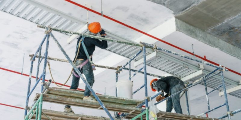
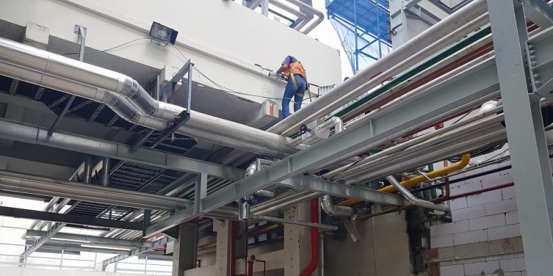
Overhead Installations
Working at height introduces additional hazards during drilling and mounting. Employ secure scaffolding or mobile elevating work platforms and ensure installers use fall protection—harnesses, lanyards, and certified anchor points. Implement dust control with vacuum‑attached bits or containment barriers to protect personnel and equipment. Plan for safe tool handling and material staging to prevent dropped objects and maintain a safe workspace.
Ventilated Cable Tray: Enhancing Heat Dissipation and Protection
Installing the Cara Pemasangan Cable Tray
Installing the hangers and mounting the cable tray sections is a crucial part of cara pemasangan cable tray. This stage ensures that the cable tray system is properly supported and securely positioned, allowing for the safe and efficient management of electrical cables. If done correctly, it minimizes the risk of tray failure, reducing the need for frequent cable tray replacement.
Attaching Tray Supports
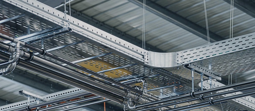
Tray supports form the backbone of the installation, bearing both tray and cable weight without deformation. Install supports at manufacturer‑specified intervals, using heavy‑duty brackets or wall‑mount fixtures anchored into structural elements. A stable support framework maintains tray alignment and preserves cable organization over time.
Fixing the Hangers into Position
Selecting the Right Hangers
In the installation of cable tray and support systems, choose hangers rated to support both the empty tray and its fully loaded cables—with extra capacity for dynamic loads and future additions—by consulting manufacturer load tables for proper material, gauge, and spacing, selecting finishes suited to site conditions (e.g. high humidity or chemical exposure), and ensuring all hangers comply with relevant safety standards to prevent overstressing and guarantee long‑term stability.
Aligning the Hangers
Begin by marking the exact path of the cable tray on the mounting surface, using a laser level or chalk line to maintain a straight route. Position hangers at uniform intervals—typically every 1.5 to 2 meters—ensuring each aligns precisely with the marked line. Consistent alignment reduces joint stress, simplifies tray installation, and minimizes the risk of misalignment‑induced strain on cables.
Securing the Hangers
After alignment, drill pilot holes at the marked positions using bits suitable for the substrate (masonry, concrete, or timber). Insert anchors or sleeves as specified, then tighten fasteners—such as toggle bolts or expansion anchors—until the hanger is firmly seated without wobble. Verify each hanger’s stability by applying moderate manual force; properly secured hangers prevent loosening under load or vibration over time.
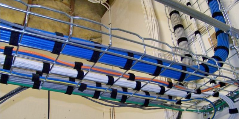
Mounting Cable Tray Sections
Starting with the First Section
Install the initial tray segment by sliding it onto the secured hangers and ensuring its flanges rest evenly within each hanger saddle. Confirm the section sits flush with the pre‑marked route and leaves sufficient clearance—around 40 mm—above the board or conduit for cable installation. Tighten any carriage or fastening clips lightly, allowing for minor adjustments when aligning subsequent sections.
Securing and Aligning Sections
Use the manufacturer’s recommended bolts or clips to join adjacent tray sections, tightening each fastener evenly to achieve a snug fit without distorting the metal. As you advance, periodically check that each new section remains coplanar and level with the first. Adjustable brackets or shims can correct minor height discrepancies, ensuring a continuous, straight run that maintains optimal cable support and routing.
Inspection and Final Adjustments
Once all sections are in place, inspect every joint and hanger for tightness and proper engagement. Employ a spirit level to verify horizontal alignment and apply a feeler gauge to check for gaps at seams. Adjust hanger heights or retighten fasteners where deviations exceed 5 mm. A thorough final check guarantees a secure, level installation, ready for safe and efficient cable loading.
Additional Considerations
- Tray Spacing: Allow enough distance between parallel trays to facilitate cable access and prevent overheating.
- Future Expansion: Leave extra capacity for additional cables, ensuring the system can grow without major modifications.
- Environmental Resistance: In outdoor or corrosive settings, opt for stainless steel or galvanized components to resist rust and weathering.
Top Features of High-Quality PV Cable Trays for Solar
Cara Pemasangan Cable Tray: Connecting Grounding at Each Joint
In cara pemasangan cable tray, grounding is an essential step to ensure the system operates safely. Proper grounding prevents electrical faults and helps avoid dangerous situations such as electric shocks or fires. By grounding the cable tray at each joint, you ensure the system is compliant with safety standards and can handle electrical currents without risk.
Grounding the Cable Tray System
Grounding the cable tray system is a vital safety measure. It provides a pathway for electrical currents to flow safely to the ground in the event of a fault. A properly grounded tray reduces the risk of damage to cables and electrical equipment, and ensures the safety of workers who may interact with the system.
- Prevent Electrical Faults: Provides a safe path for fault currents (e.g., during a short circuit), protecting both the tray and enclosed cables.
- Protect Personnel: Prevents the tray from becoming energized, reducing the risk of electric shock to anyone who touches it.
- Meet Regulatory Requirements: Electrical codes worldwide mandate that metallic cable trays be grounded for safety and compliance.
Grounding Methods
Grounding Conductors
Copper or aluminum conductors sized to handle the system’s maximum fault current form the backbone of a reliable grounding network. At each tray joint, a grounding clamp securely fastens the conductor to the tray’s metal surface, ensuring a low‑resistance connection. The conductor is then routed back to the main grounding busbar or grounding electrode, creating a continuous, unbroken path that safely diverts fault currents into the earth.
Bonding with Grounding Straps
Flexible straps made of copper or galvanized steel bridge adjacent tray sections, maintaining electrical continuity across seams. To install, lay the strap over the overlapping flanges of two tray segments, then tighten with bolts or dedicated bonding clamps. It’s crucial that the strap contacts bare metal—free of paint, rust, or debris—to minimize resistance and guarantee that any fault current can flow unimpeded through the tray system.
Grounding Supports and Hangers
Tray supports and hangers must be integrated into the grounding loop to prevent floating potentials on the support hardware. Attach a short grounding conductor or clamp from each support piece back to the primary grounding conductor or busbar. This ensures that, in the event of a fault landing on a support bracket or hanger, the fault current still has a direct route to ground, protecting both personnel and equipment.
Benefits of Proper Grounding
Improved Safety
A well‑grounded cable tray dramatically lowers the chance of electric shock or fire by channeling fault currents directly to earth. Should insulation fail or conductors come loose, the grounding system activates overcurrent protection devices—like breakers or fuses—more reliably and quickly. This rapid response prevents excessive heat buildup and sparks, safeguarding both personnel and surrounding infrastructure.
Enhanced Reliability
Grounding mitigates the harmful effects of stray or induced currents that can disrupt sensitive equipment. By providing a stable reference potential, it minimizes electromagnetic interference and voltage fluctuations across the tray network. The result is fewer unexpected shutdowns, reduced data errors in connected devices, and a more predictable maintenance schedule—ultimately keeping operations running smoothly.
Extended Service Life
Proper grounding helps prevent electrochemical corrosion, which occurs when dissimilar metals develop a voltage difference in the presence of moisture. By bonding all tray sections and supports to the same potential, you eliminate these differential voltages. This uniform grounding environment preserves metal integrity, prolongs the lifespan of both the cable tray and the insulated cables it carries, and reduces replacement costs.
Code Compliance
Adhering to grounding requirements in standards such as the NEC, IEC, or local regulations is essential for passing inspections and securing insurance coverage. Proper grounding eliminates the risk of enforcement actions, fines, or forced system shutdowns due to noncompliance. It also demonstrates a commitment to industry best practices, enhancing credibility with clients and regulatory bodies.

As the editor of GangLong Fiberglass, I have years of experience and in-depth research, focusing on cable tray products, fiberglass solutions, and grille systems. I incorporate years of industry insights and practical experience into every content, committed to promoting the progress of the industry. At GangLong Fiberglass, my commitment is reflected in every product, from innovative cable trays to durable fiberglass solutions and sturdy grille systems. As an authoritative voice in the industry, my goal is to provide valuable information to professionals and businesses and promote forward-looking solutions.